Vehicle Dynamics Control proline (ABS, EDS, ASR, ESP)
- Availability: On Order
- Brand: Thepra
- Product Code: 136035250
- Product viewed: 30147
Share:
Vehicle Dynamics Control proline (ABS, EDS, ASR, ESP)
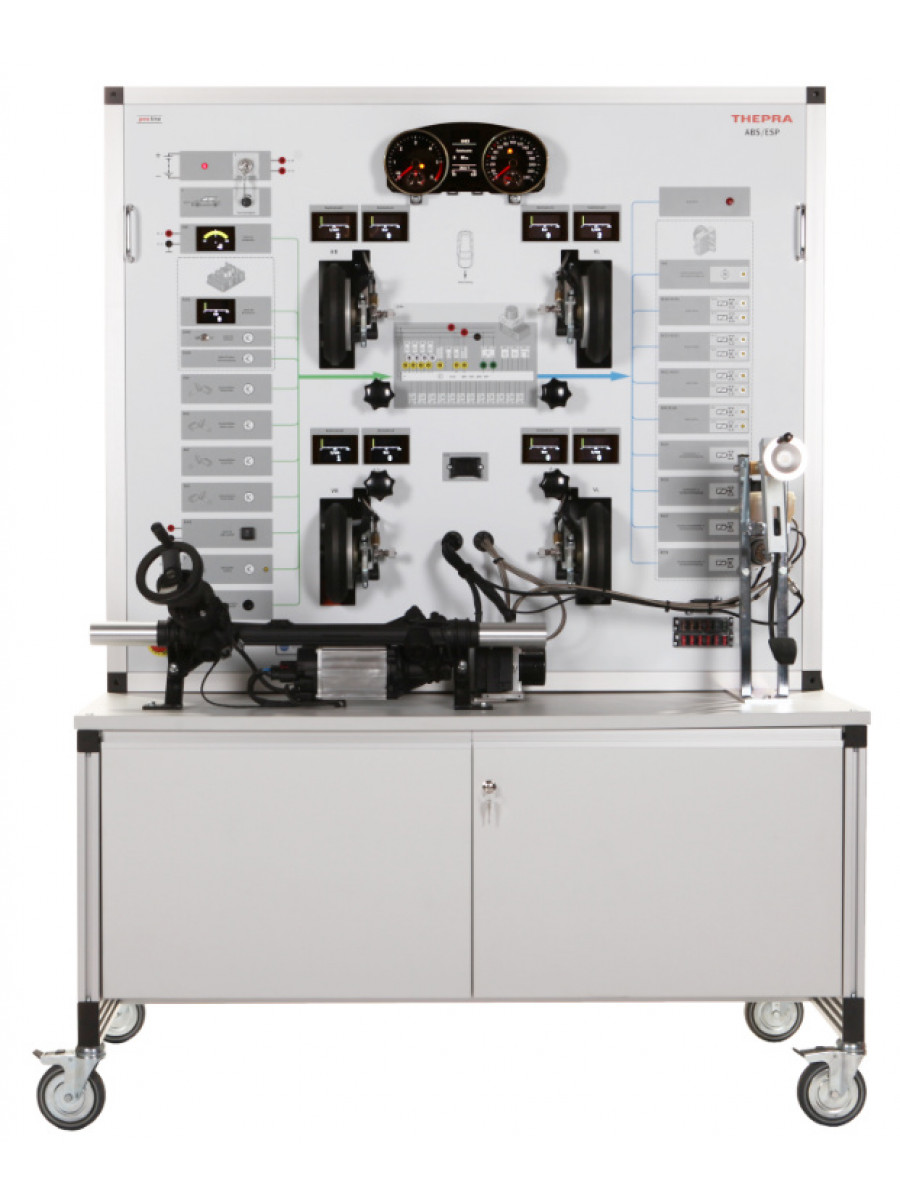
With this teaching and training rig all functions and processes, errors and measuring values can be demonstrated and examined as they are in the original brake system with vehicle dynamics control. The fully functional brake system brakes the individual wheels depending on operating and control conditions. Regular braking, ABS, ASR, EDS, ESP or individual wheels. All original parts and required components are clearly arranged in the IPO-principle on the color printed front panel. The required power supply, wiring and component configuration are already integrated into the system and preset, ready for operation. This means the system can be put into operation immediately upon setup.
- At a glance
- Features
- Vehicle dynamics control, original Golf VI components, with electromechanical power steering
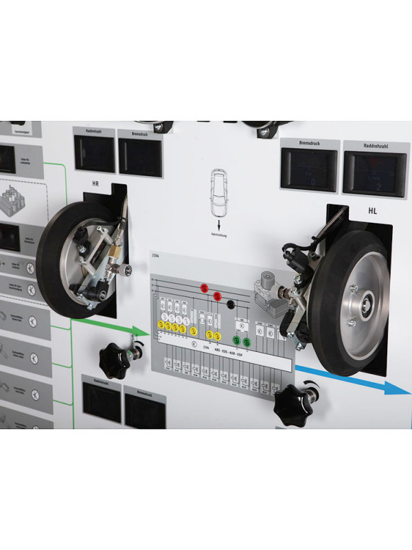
- Measuring of all relevant parts and components in the central circuit diagram measuring field
- Arrangement in the IPO principle: input - processing - output
- Acceleration and brake force transfer values can be set separately for each wheel
- Values for steering angle and brake pressure can be read on digital display units. The brake and the wheel speeds are shown for each wheel with digital color displays.
- ESP functions are indicated to the vehicle dynamics controller by the CAN-BUS via steering wheel and steering angle encoder
- Skidding simulation with and without brake intervention
- Steering intervention of the ESP in the electromechanical steering with parallel axis drive is represented very vividly
- Speed adjustment from 0-60 km/h can be set continuously
- Can be diagnosed via OBD interface
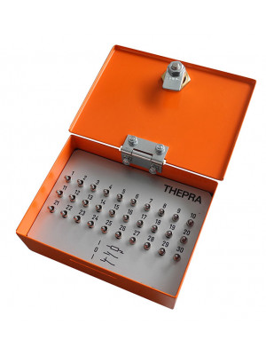
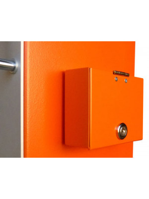
- Fault circuit, lockable by a lid
- Connection for student circuit diagram measuring desks
- Compact device build, mobile, for lab and workshop practice
- Learning Objectives
- Vehicle dynamics control: Naming components of the entire brake system and explain their interaction
- Working with original schematics and specify problem-oriented connector pins on components and control unit
- Determining reference values depending on operating situation
- Using common OBD diagnostic tools for the workshop
- Measuring and assessing sensor signals and actuator control voltages, recording CAN-bus signals with the oscilloscope and assessing signal levels
- Making screen-shots of all signals, all control voltages and the CAN data-bus with a digital oscilloscope and storing them for customer-specific documentations
- Examples for exercises
- examine the influence of the various sensors on the different actuators
- recording and evaluating the actuation of the actuators corresponding to the input values
- recording and assessing pressure situations in the system and at the individual wheels depending on the corresponding control of the actuators
- demonstrate braking with and without ABS, by wheel, by axle or in total
- demonstrate the ASR function, by wheel, by axle or in total
- demonstrate the ASR/EDS function
- demonstrate the ESP function, understeering, oversteering, contra skidding, with or without braking
- demonstrate, record, and evaluate practice-oriented errors
- carry out error diagnosis via the fault reader
- Equipment
- Proline system cart with cabinet, construction in a closed housing
- Front panel design with color digital printing, circuit diagrams, components and symbols, protective film
- 10 x large digital color displays
- Inputs: ignition switch, ASR/ESP switch, hand brake control switch, switch for brake actuation and brake lights, rotational speed sensor for right/left front wheel, rotational speed sensor for right/left rear wheel, sensor for brake pressure, control device for engine management, electromechanical steering with parallel-axis drive
- Processing: vehicle dynamics control unit, diagnosis connection for original tester
- Outputs: indicator lights / error lights on ABS / ESP / steering in the original instrument panel, hydraulic pump for vehicle dynamics control, hydraulic power pack with all intake valves and discharge valves, on-off valve -1 & 2- vehicle dynamics control, high-pressure on-off valve -1 & 2- vehicle dynamics control
- 20 x measuring sockets in 4mm safety version
- Detailed documentation and extensive worksheets for teachers and students
Engineering
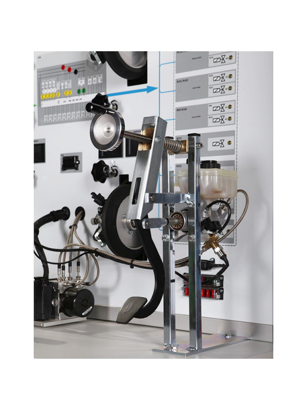
The four wheels are driven via adjustable friction rollers which are powered by an electric motor with freely adjustable speed. The fully functional brake system brakes the individual wheels according to the operation and control situation. Normal braking, ABS, ASR, EDS, ESP, or decrease in braking pressure for ABS on the individual wheels. Wheel rotating speed and brake pressure of the individual wheels, system pressure, pedal force and vehicle speed are read from digital display devices. Control of the individual valves and the hydraulic pumps are displayed on LED's.
For simulation of the ESP functions the drivers requirements are transferred to the vehicle dynamics control device via the steering wheel and steering angle sensors by the CAN-BUS. In addition, depending on the driving speed and wheel angle, the various driving and control conditions such as insufficient turning, excessive turning, contra skidding with or without braking are produced.
Technical Specifications
- Power supply: 400 V, 16 A
- Dimensions: W x D x H: 141 x 70x 193 cm
- Weight: about 185 kg

